On 4/21/09 (Tuesday) we were paired up and revisited two site here on campus, the basketball facility and the New Res. Hall.
Similar:
One major similarity was the site layout utilization and its housekeeping. At both sites, there was parking on site for laborers. The area was fenced off, trailers were on site, and work was in progress.
Another similarity dealt with the materials on site. On both sites, there was plenty of materials which were eventually going to be used on the project (both sites had mortar mixers and other materials and equipment). Also on both sites, equipment was sitting idle. These both would fall under management of the project manager and under cost control aspects.
A more general comparison would be the overall design commonality. Both projects, yet different, were following the typical Virginia Tech design which includes Hokie Stone. Both sites had mock panels for quality and construction purposes.
Differences:
One of the first major differences I noticed was how each site was organized. At the New Res. site, materials were just piled on top of each other and in the way of workers. There was not nearly as much organization as the basketball facility. This would fall under site utilization of the project.
I also noticed at the New Res. site that there was plenty of still water sitting in the strip footing ditch, which is not a good thing. They type of building that is under construction also has an effect on the means and methods in the different construction practices.
Another difference was location. Most importantly, the location of the New Res. building was in the middle of major pathways right on campus, therefore space was limited. The basketball facility is still on campus, however in the back of campus where students are farther away from getting in the way, therefore allowing more space for the construction site. This all allowing different practices in handling materials and equipment.
Tuesday, April 21, 2009
Tuesday, March 17, 2009
Industry Day
 This is a model for a pick show before the actual pick. There are several steps to do before you can begin. First we must know the physical weight of the object we are trying to pick. This model was about 300 lbs. The next step is to measure the radius to the center of where we are going to place the pick.
 We must then calculate if we are able to make the pick. Reading the label on the rig strap will tell us another important calculation which we must factor in.
 After the calculation, we can make the pick by far. So we attach the tag line to the bottom. Greg and Rusty are overseeing that this process is being done correctly.
 Using the OSHA list of hand signals, we are able to hoist the object and begin to place it in the right position. This hand signal is "boom out".
 Spectra I.S. "The Future"
 With this new equipment, the past days of staking points and point generation are long gone. Now drawings will be sent straight to the site and the owner instantly. Not only that, but graders will be able to automatically adjust to the exact grading needed on a specific area of soil. Less work for the grader and just as accurate. Spectra I.S. is the future.
 One of my fellow students training on the simulator here at Industry Day.
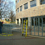 |
| Link to Industry Day Phot album via Picasa |
Sunday, March 1, 2009


This sketch is for the drip pan underneath a cooling unit on the third floor. It is suspended underneath the unit by four steel cables. These steel cables support the drip pan and are mounted in the dropped ceiling. The drip pan is nothing more than a thing piece of metal rounded on all sides to catch the "dripping" water.

This sketch has three sketches in it. One is a section of one of the stairwells in our newly built construction classroom building. The section is cut through the upper portion of the stair case. In order to show more detail, I did not repeat the lower portion of the staircase. As you could imagine it continues around to the bottom, and looks almost identical.
The second and third sketch are the detail in each step up into the landing. This sketch is the top two stairs into the upper landing. Notice the tread pan shape and where the concrete is poured. Also notice the steel channels in both sketches.

This is the plan sketch of the stairwell. The above sketch is the section if we were to cut the left staircase down the middle and would look towards the left wall.

This sketch shows the section through a door and through a window in my apartment room. My apartment is wooden frame constructed, and the window is a simple double hung. I labeled some of the important details.

This sketch is a plan view of my apartment in Maple Ridge. The door which I sketched above is the door which leads into my room. You can also see where the window is in the apartment.
Thursday, February 26, 2009
Maple Ridge Construction
2/26/08 2:00-2:30 p.m.
 Maple Ridge is currently working on expanding their supply of their popular 4 person townhouses. A lot of construction has already started and been erected. I hear it every morning because it wakes me up. However this is a good chance to watch the whole entire process of a familiar townhouse.
In this picture you can see somewhat the desired goal.

Not too much action was taking place in the lot directly to the left of the erected townhouses. But here you can see they are excavating the huge slope into a flat, workable lot to build on.

Here you can see the CMU blocks which are built on top of the concrete foundation. This is in between the previous plot picture and the townhouses which were in the first photo.

This construction is to the right of the townhouses in the first picture. As you can see workers are putting 2x4 s into place for the main building frame. One worker is on top nailing down the top 2x4. The others are placing down sheathing on the floor.

Once the framing is complete, workers will place side sheathing. This picture shows what will be the next couple of steps.
 I took this photo to point out the heading. This is done so that it will support the area in which a large window will be placed, probably for the main living room area.
Subscribe to:
Posts (Atom)


